
Do you want to environmentally recharge 3V batteries? All you need to do is read this article to find the solution!!! This article presents a low-cost way to design a solar battery charger.
The setup is centered around a solar panel. This panel should provide a voltage close to 3.6V, which is the sole requirement.
To locate such a solar panel, you can salvage cells from small garden lights. However, a single one of these cells won’t suffice. Therefore, it’s necessary to connect several of them in series to create a voltage as close as possible to 3.6V.
In a series configuration, voltages add up, and the current passing through the circuit remains consistent throughout.
On the other hand, in a parallel arrangement, voltages remain the same, but currents add up at the junction nodes.
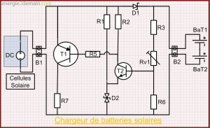
Electrical diagram for mounting a solar battery charger
List of components and theoretical cost
Component details
Terminals facilitate easy wire connections but are not essential.
A battery holder is also recommended for easy battery connection.
Similarly, if you cannot create a printed circuit board (the PCB design will arrive one day), purchase a perforated board to serve as a support. Given the complexity of the assembly, this will be more than sufficient.
Functioning
The functioning principle is quite straightforward: we continuously monitor the voltage across the batteries. Once it reaches a specific threshold, the current is redirected away from the batteries and directed toward a power resistor.
This uncomplicated setup doesn’t necessitate expensive components (except for the solar panel) or the need for programming microcontrollers. Furthermore, the assembly’s simplicity enables adaptation to different battery types. All that’s required is adjusting the output voltage of the solar cells to match the battery capacity.
Increasing the number of solar cells also reduces battery charging time. As a rough estimate, it typically takes around 12 to 14 hours to fully charge 1400 mAh batteries.
Initialization
To make the charger operational, a minor adjustment is necessary, which is where potentiometer P1 comes into play. The values marked on the components carry a margin of error, and the procedure is quite straightforward.
Begin by sourcing a constant voltage power supply and set it to a slightly lower voltage than the sum of the battery voltages. As a reference, a 1.5V battery is considered fully charged when its terminal voltage reaches 1.44V. Following the article’s instructions, you should adjust the power supply to 2.88V.
The objective of this process is to determine the switching point between charging and discontinuing the charge. The power supply simulates the presence of charged batteries.
. Next, place a voltmeter (a device for measuring voltage) across the terminals of R7.
. Set the potentiometer to its maximum value.
. Connect the power supply outputs in place of the battery outputs.
. Position the solar cells in direct sunlight.
. In theory, the voltage across R7 should be close to zero as the batteries charge. Gradually reduce the potentiometer value.
. As soon as the voltage across the potentiometer terminals abruptly increases, cease adjusting the potentiometer. T1 has just switched, interrupting the battery charging process.
Now, it’s calibrated and ready to charge batteries.
Source: energies2demain.com Creative Commons